간단한 예제....
결국 많은 라이브러리 제대로 동작되지 않아, AT명령으로만 구성.
필요한 소스는 다른 라이브러리를 참조해서 작성해야 할 듯....
- AT명령 참조할 것. https://room-15.github.io/blog/2015/03/26/esp8266-at-command-reference/
- 아두이노 보드와 SoftwareSerial 해서 ESP8266 를 통해 wifi는 느리므로, ESP8266 으로 Server 구성해볼 것.
. 아두이노 UNO보드를 이용해서 ESP826 칩으로 업로드하려면, atmega328p 칩을 제거해야함.
#include <SoftwareSerial.h>

#define DEBUG true

SoftwareSerial esp8266(2,3); // make RX Arduino line is pin 2, make TX Arduino line is pin 3.
                             // This means that you need to connect the TX line from the esp to the Arduino's pin 2
                             // and the RX line from the esp to the Arduino's pin 3

unsigned int count = 0;

void setup() {
    Serial.begin(9600);
    esp8266.begin(9600); // your esp's baud rate might be different

    Serial.println("");
    Serial.println("ESP8266 ESP-01 module");
    Serial.println("");

    sendData("AT+RST\r\n",2000,DEBUG); // reset module
    sendData("AT+CWMODE=1\r\n",1000,DEBUG); // configure as access point
    sendData("AT+CWJAP=\"U+Net5B6F\",\"1000019118\"\r\n", 5000, DEBUG);
    sendData("AT+CIFSR\r\n",1000,DEBUG); // get ip address
    //sendData("AT+CWSAP=\"esp8266_j2h\",\"12345678\",5,3\r\n",1000,DEBUG); // ap모드
    sendData("AT+CIPMUX=1\r\n",1000,DEBUG); // configure for multiple connections
    sendData("AT+CIPSERVER=1,80\r\n",1000,DEBUG); // turn on server on port 80
}

void loop() {
  if(esp8266.available()) // check if the esp is sending a message
  {
    if(esp8266.find("+IPD,"))
    {
     delay(1000);

     int connectionId = esp8266.read()-48; // subtract 48 because the read() function returns
                                           // the ASCII decimal value and 0 (the first decimal number) starts at 48

      String response = "";
      while(esp8266.available()) {
        // The esp has data so display its output to the serial window
        char c = esp8266.read(); // read the next character.
        response+=c;
      }

     if(DEBUG && response.length() > 0) {
      Serial.println("\r\n------------------ response start");
      Serial.println(response);
      Serial.println("------------------ response end");
     }

    String webpage = "";
    //webpage  = "HTTP/1.1 200 OK\r\n";            // 크롬, IE는 해더로 인식하나, ios에서 인식 안함.
    //webpage += "Content-Type: text/html\r\n";
    //webpage += "Connection: close\r\n";
    //webpage += "Refresh: 10\r\n";
    //webpage += "\r\n";
    webpage += "<!DOCTYPE HTML>\r\n";
    webpage += "<html><body>\r\n";
    webpage += "<h1>Hello</h1><h2>World! " + String(count++) + "</h2><button>LED1</button><button>LED2</button>\r\n";
    webpage += "</body></html>\r\n";

     String cipSend = "AT+CIPSEND=";
     cipSend += connectionId;
     cipSend += ",";
     cipSend +=webpage.length();
     cipSend +="\r\n";

     sendData(cipSend,1000,DEBUG); // cipsend - maxlength 2048
     sendData(webpage,1000,DEBUG);
     /*
     webpage="<button>LED2</button>";

     cipSend = "AT+CIPSEND=";
     cipSend += connectionId;
     cipSend += ",";
     cipSend +=webpage.length();
     cipSend +="\r\n";

     sendData(cipSend,1000,DEBUG);
     sendData(webpage,1000,DEBUG);
     */
     String closeCommand = "AT+CIPCLOSE=";
     closeCommand+=connectionId; // append connection id
     closeCommand+="\r\n";

     sendData(closeCommand,3000,DEBUG);
    }
  }
}

String sendData(String command, const int timeout, boolean debug)
{
    String response = "";
    esp8266.println(command); // send the read character to the esp8266
    long int time = millis();
    delay(20);

    while( (time+timeout) > millis()) {
      while(esp8266.available()) {
        // The esp has data so display its output to the serial window
        char c = esp8266.read(); // read the next character.
        response+=c;
      }
    }

    if(debug && response.length() > 0) {
      Serial.println("\r\n------------------ response start");
      Serial.println(response);
      Serial.println("------------------ response end");
    }

    return response;
}

void clear() {
    while (esp8266.read() != -1) {}
}
728x90
'Programming Language > 아두이노, 라즈베리파이' 카테고리의 다른 글
| ESP8266 라이브러리, 예제 (1) | 2024.01.08 |
|---|---|
| ESP8266 샘플 많은 곳 (1) | 2024.01.08 |
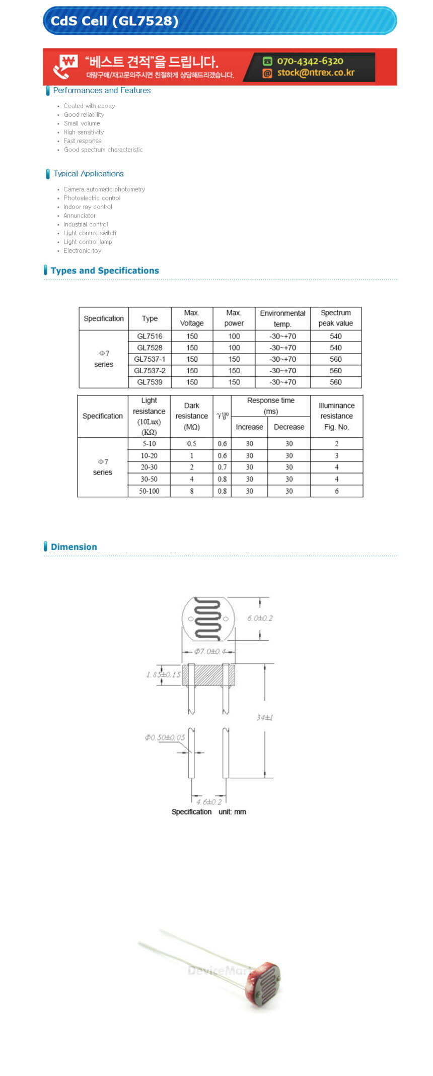
| 광센서 CdS Cell (GL7528)/Light Sensor (0) | 2024.01.08 |
| DHT11 온습도 센서모듈 [SZH-EK024] (0) | 2024.01.08 |
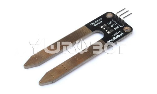
| Soil Moisture Sensor Module [SEN030003] (0) | 2024.01.08 |